Capacitive Sensing Can
This is a short summary of a project taken as part of an analog electronics class taken by me and a colleague at Lund University in 2016. The full paper is here.
Background
The idea for our project came from the Theremin. We aimed to build a theremin type instrument as simply as possible, using drinks cans as sensors if possible. The easiest way to do this is by attaching a relaxation oscillator to a resistive (or inductive) and capacitive element. The equation for the state of a capacitor is
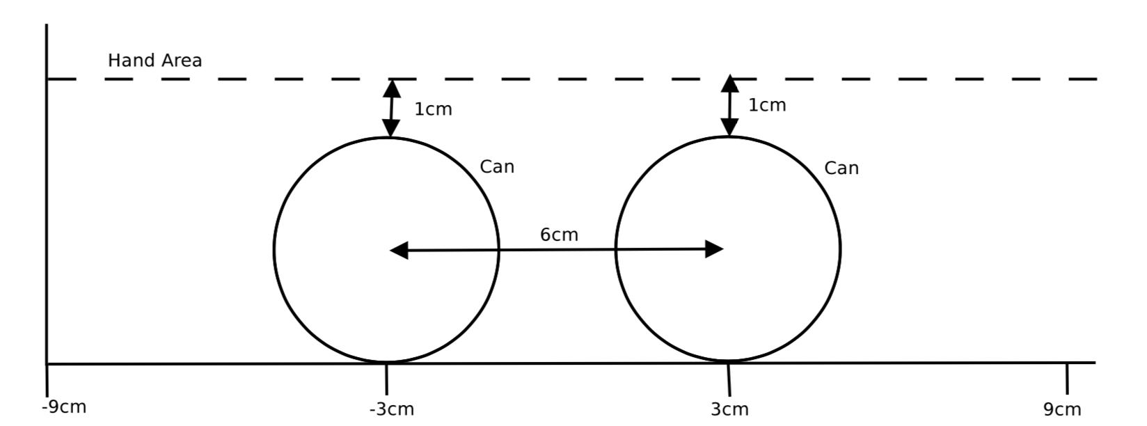
\[i = Cdv/dt\]The current, \(i\) is known and to find \(dv/dt\) we must measure the charging time of the capacitor. These two numbers are used to calculate C: The Capacitance of the object. The capacitance of a surface changes when some other object comes near to it. This is because everything has a capacitive field of some order which interact with eachother. Capacitive sensing is used in countless technologies to sense objects for this reason. Aluminium has a relatively high natural capacitance so drinks cans were a decent option, we hoped that our circuit would be sensitive enough to pick up our hands aswell.
Design
Relaxation Oscillator
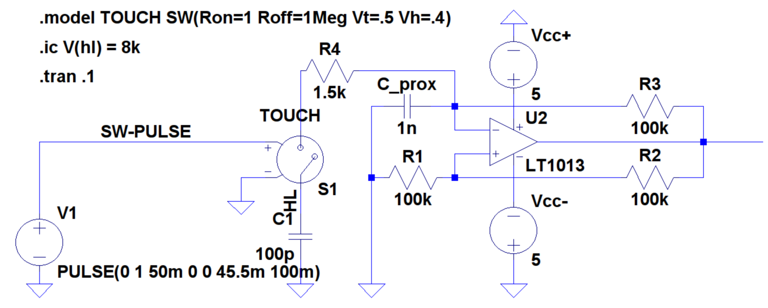
The schematic above is our equivalent relaxation oscillator built in LTSpice for simulation. The power supply is pulsed every 50ms to simulate a finger touch. \(C1\) is the capacitance of the finger or body which may be touching the circuit. Every 50ms \(C1\) and \(R4\) are engaged into the circuit which combine with \(Cprox\) and \(R1-R3\). LT1013 is a simple operational Amplifier that supplied by 5V which allows us to operate it as an XOR gate which is dependent on C1. In simple terms the op-amp will charge the capacitors until they’re saturated then invert the output, creating a square wave with frequency related to the capacitance.
FM Demodulator
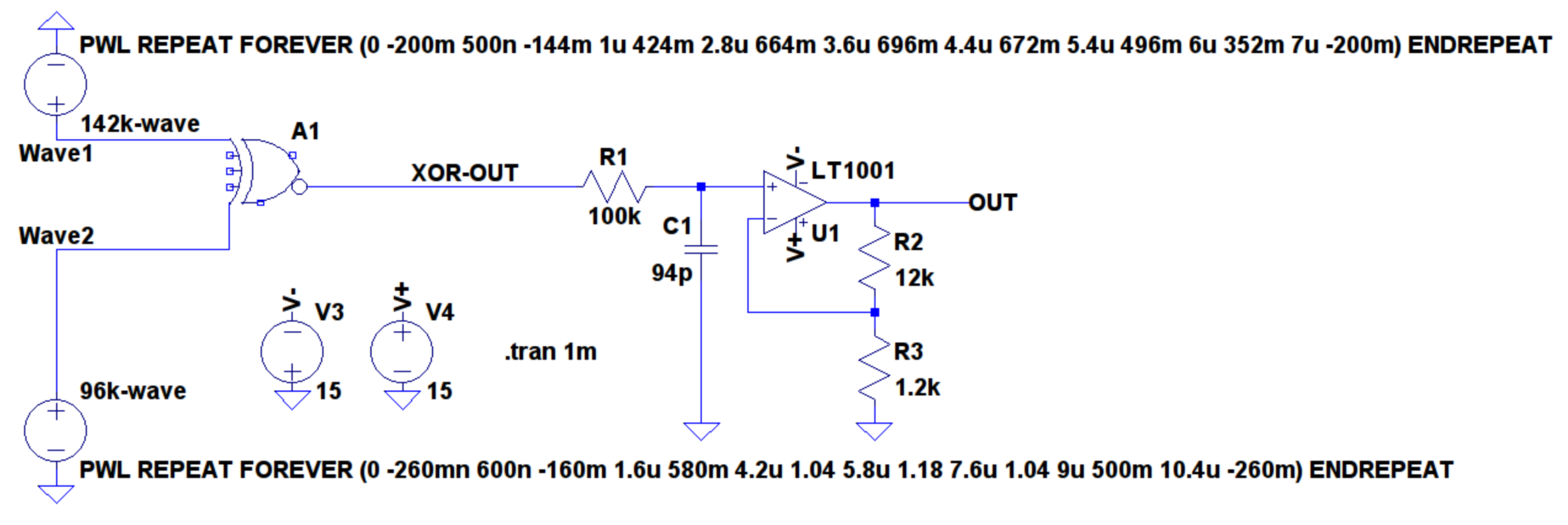
The above schematic, also made in LTSpice, represents the FM demodulator that is used to convert the oscillators change in frequency to a signal that can be played through an audio speaker. The two input signals are compared through a simple XOR as a very simple measure of correlation. The signal goes through a low pass filter to remove some noise and then amplified to ensure sufficient volume.
Construction
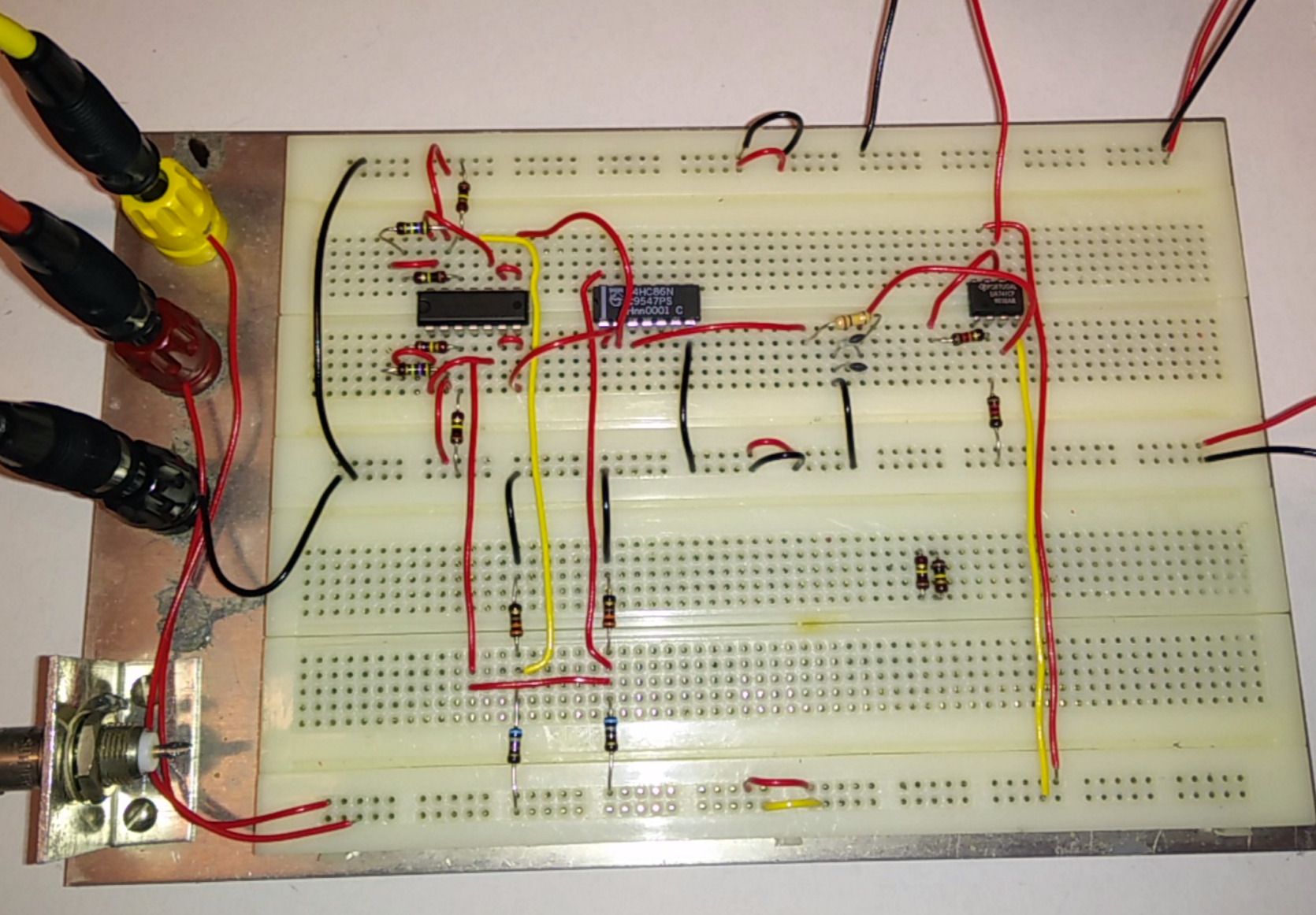
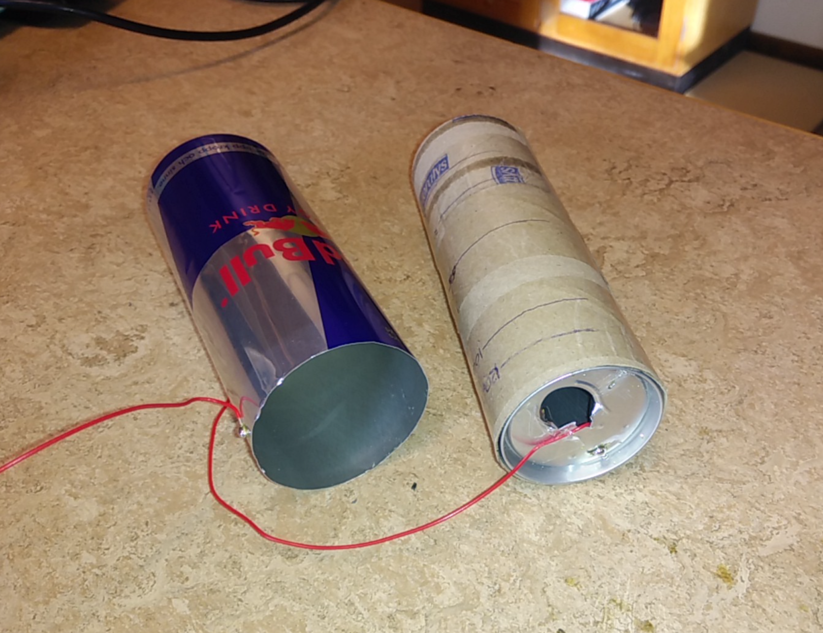
The final construction of our circuit involved a simple breadboard with out oscillator and demodulator connected at one end to two aluminium cans and at the other end to a small speaker. We found that using aluminium cans had an advantage as they can be modelled as a very wide coaxial cable. After some experimenting we found the best results came from partially shielding one can with cardboard, the result of which is shown below.
Testing
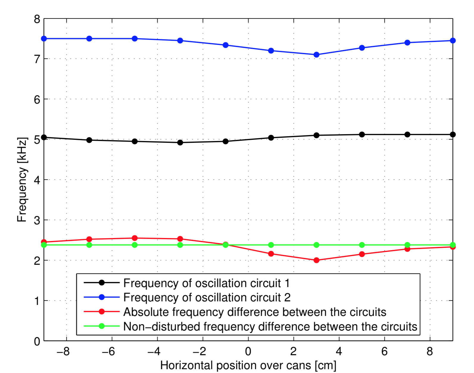
With the final circuit in place we undertook a lot of testing and tuning to ensure the circuit was sensitive enough and in the right frequency range to be heard. Waving a hand over the two can capacitors triggers the XOR gate and produces a sound which varies depending on the location and direction of the moving hand. The graph below shows the final result, the red line shows the subtle drop in absolute frequency difference as a hand moves over which could be heard through the speaker.
There were many puzzles and problems during this project but each exhibited a different aspect of analog electronics. There is much room for improvement on our design, specifically the cans could be moulded to form a more receptive shape which would increase sensitivity. The breadboard circuit is shown below.