Analysis of a Permanent Magnet Synchronous Machine
This is a summary of a project completed along with two fellow students at Lund University in 2016. The full paper can be found here, the paper is based on preparation assignments 1, 2, 3, 4, & 5
Introduction
This project is a technical feasability study on magnetic rotors, their qualities and restrictions. When I first started the study it was the first time I had encountered most of the mechanical terms, equations and methods laid out in the assignments for this module, including the Finite Element Method.
Our aims for the project are to design a magnetic machine that would deliver enough torque for an electric bike application, while maintaining appropriate size, weight, and efficiency. This is to be achieved through:
- Calculation
- Equivalent circuit analysis with MATLAB
- Finite Element Method analysis with FEMM
Initial Calculation
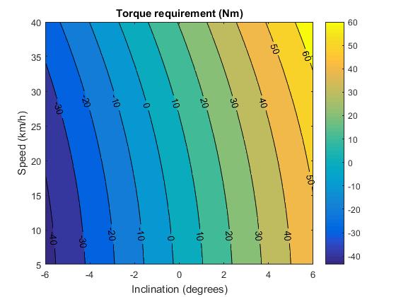
The first stage is to lay out some fundamental assumptions about the application of the machine. In this case it was to be used within a bicycle wheel; this imposes restrictions on size and weight. We also assume a rider weight of 80Kg and bicycle weight of 20Kg with 0mph wind speed. We show that the required power and torque are dependent on the various forms of resistance.
\[Power=((Fdrag + Froll + Fgrav) * v)/0.8\] \[Torque = P/w\]Input into MATLAB while varying inlination and speed gives the output shown by figure 1.
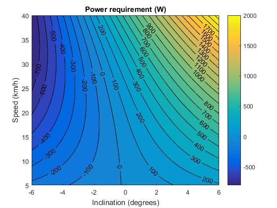
Equivalent Circuit
The output of the initial simulations is fed back into MATLAB using the equivalent circuit method to find the required machine sizes for different torque outputs. The output of these secondary simulations is shown in Figures 2 & 3.
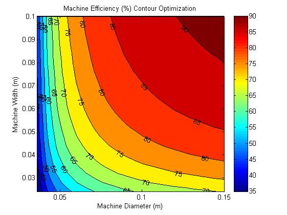
The equivalent circuit method is much less accurate than finite element but it helped us narrow down the choices for machine size. Our aim for power output is 250W, therefore it was judged to use a diameter of 90mm, width of 80mm going forward.
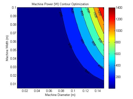
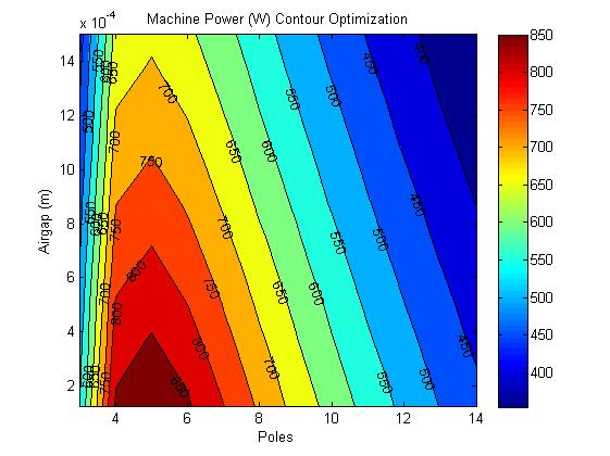
After more equivalent circuit simulations it can be shown that the effect of the number of magnetic poles on the output power is much greater than size or magnetic air gap. Figure 3 shows the result of varying air gap and number of poles on output power for a 90mm by 80mm machine.
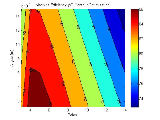
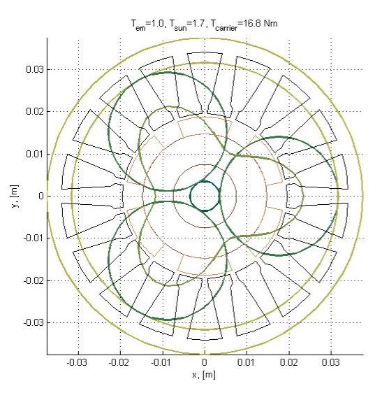
It has been determined from the equivalent circuit simulations that power and number of poles are the most important factors as a gear can be used to adjust our torque if there is enough power. A new script is run to determine the optimal size for a 200W, 6 pole machine with a planetary gear. The output is shown in Figure 6, it has a diameter of 75mm and width of 47.5mm.
Finite Element Method
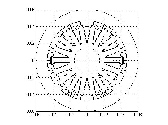
The finite element method was applied via the FEMM program, called from MATLAB and applied to the inner and outer rotors seperately.
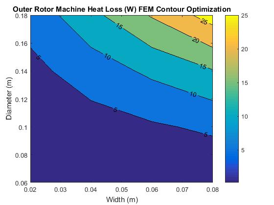
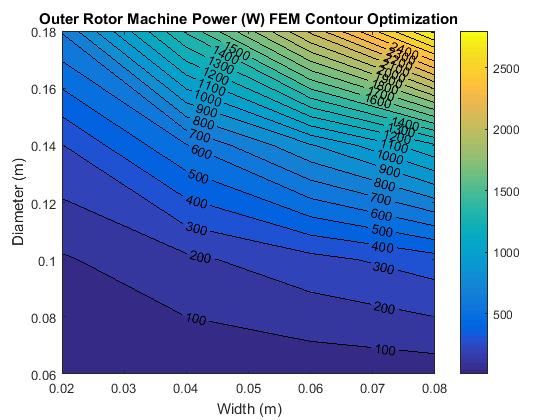
Figure 6 shows one of the output diagrams and shows significant variation from the equivalent circuit diagrams. We conclude that this variation is due to the FEM being purely 2D and not accounting for losses in the third dimensions which would grow proportionally larger with a lower diameter.
The next stage is to compare the inner and outer rotor topologies for temperature distribution and flux density.
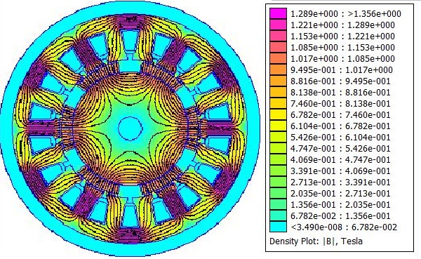
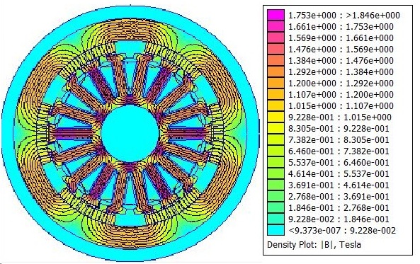
The inner rotor seems to display a better spread of flux density compared to the outer. For the heat distribution it is the opposite so the differences in design choice may not be very different. The harmonics are also analysed and judged to be satisfactory.
Conclusion
The results from all the simulations are processed and digested to inform the decision of the final design parameters. The final design drawing is shown in figure 11.
| Width | Diameter | Poles | Air Gap | Rotor Position | Weight |
|---|---|---|---|---|---|
| 80mm | 120mm | 6 | 0.8mm | Outer | 3.5kg |